A digital optical encoder is a device that converts motion into
a sequence of digital pulses. By counting a single bit or by
decoding a set of bits, the pulses can be converted to
relative or absolute position measurements. Encoders have
both linear and rotary configurations, but the most common
type is rotary. Rotary encoders are manufactured in two
basic forms: 1) the absolute encoder where a unique digital
word corresponds to each rotational position of the
shaft, and 2) the incremental encoder, which produces
digital pulses as the shaft rotates, allowing measurement of
relative position of shaft. Most rotary encoders are
composed of a glass or plastic slotted disk. As radial
lines in each track interrupt the beam between a photoemitter-
detector pair (or Optointerrupter), digital pulses are produced.

Inexpensive rotary encoder
The circuit outputs are high as default. When the spindle
is turned, there will be pulses on the outputs. The lower
square wave output signal leads or lags 90 degrees in
respect to the upper signal - it depends on the direction
the spindle is turned. The circuit works from 2V up to 36V,
so 3.3V logic works too. The LM393 gives out good pulses
with as little as 5mV differential input, which means that this
circuit works even when the motor is turned very slowly.

Rotary encoder converter circuit
This circuit used convert signal from Rotary encoder (A,B) to
two pulse signal
- Y for CCW direction
- X for CW (clockwise) direction
Two pulse signal is easy for microcontroller programing
The circuit used two D-type flip-flop(74HC74D) for the judgement.

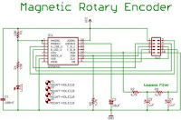
Magnetic Rotary Encoder Design
Inspired by Nopheads fantastic printing progress using his
encoder, I decided that RepRap would greatly benefit by having
an awesome, standardized rotary encoder board. The optical
encoders can be finicky and hard to mount. Many RepRappers
have also had great success in the past using AS50**
family chips, so I decided to go that route.

Rotary Encoder Counter Circuit
If we re-design the encoder to have two sets of LED/phototransistor
pairs, those pairs aligned such that their square-wave output signals
are 90o out of phase with each other, we have what is known as a
quadrature output encoder (the word "quadrature" simply refers to
a 90o angular separation). A phase detection circuit may be made
from a D-type flip-flop, to distinguish a clockwise pulse sequence
from a counter-clockwise pulse sequence:

Quadratrack: Using Mechanical Rotary Encoders
These mechanical encoders generate a "quadrature" signal. I
don't know the origin of the term quadrature but basically it
means there are four states that this device can be in. Further,
transition from one state to the next is well defined so with a
simple circuit or some software you can translate the pulses
into rotation movement.
The three pins on the device are A, B, and Common.
Since they are mechanical they are simply switches that
connect the A pin, the B pin, and then both the A and B
pin to the C pin. A simple circuit for hooking this up is shown
below


